
Structural Engineering Slide Library
Beams of various sections
|
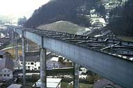
Image-GoddenA63 Elevated highway. During construction (shown) it is a continuous constant section steel plate girder. Finished, it will be a composite girder with steel beams and concrete deck. Note the shear keys on the top flange. (See also Godden Set G for more pictures of this bridge.) (Near Flamatt, Switzerland) | |
|
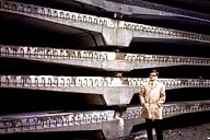
Image-GoddenA64 Elevated highway. Half-width of the precast concrete deck sections that will form the top flange of the composite section of the bridge. The bottom flat surface at the maximum concrete depth will sit on top of the steel girder flange and will lock with the shear keys. (Near Flamatt, Switzerland) | |
|
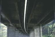
Image-GoddenA65 Elevated highway. Both girders consist of 3-web T-sections. This is a long bridge over marshy ground liable to flooding. This section does not have the torsional rigidity of a closed box section. (Near Montreaux, Switzerland) | |
|
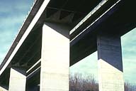
Image-GoddenA66 Highway bridge. Girder consists of a 4-web T-section over the length subjected to positive bending. Near abutments, where there is negative bending, a partial lower flange is used, tapering from the full width at the abutment to zero at the inflexion point. (Near Geneva, Switzerland) | |
|
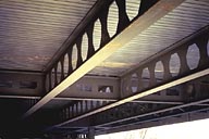
Image-GoddenA67 Castellated beams, new United Nations Building. Design controlled by bending stresses and flexural stiffness. As shear is small, web can be discontinuous. Beams made by cutting I-beams and inserting web-spacer plates. Reverse situation in GoddenA69, a deep beam controlled by shear. (Geneva, Switzerland) | |
|
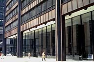
Image-GoddenA68 Daley Center Building. This large steel frame building is made of Cor-Ten steel. Of interest here is the use of heavy plate girders of the type used in bridge construction. In this case, in contrast to that of GoddenA67, shear forces are high and shear stiffeners are used throughout. (Chicago, Illinois) | |
|
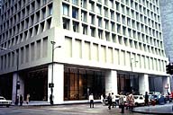
Image-GoddenA69 Brunswick Building. Note the deep concrete beams at the top of the ground columns. These 168-ft beams, supported on four columns and loaded by closely spaced fascia columns above, are 2 floors deep. Shear stresses and failure mechanisms were studied on a small concrete model. (Chicago, Illinois) |
 Set A: Beam Structures
