
Structural Engineering Slide Library
Box girders: variable depth
|
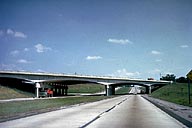
Image-GoddenA51 Freeway overpass bridge. Designed as a 4-span variable depth concrete box girder. (Near St. Louis, Missouri.) | |
|
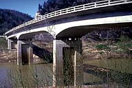
Image-GoddenA52 Continuous concrete highway bridge. This bridge is continuous over three spans, the depth being increased over the two internal supports. (Wilmore, Kentucky) | |
|
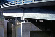
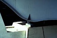
Image-GoddenA53 Detail of continuous concrete highway bridge showing end support of continuous spans and support of simply supported approach span. The former support permits axial movement due to thermal expansion and creep in the continuous spans. The latter is a hinged support. (Wilmore, Ky.) | |
|
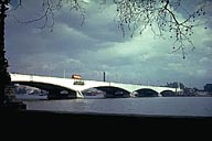
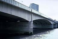
Image-GoddenA54 New Waterloo Bridge over the River Thames. Completed in 1944 this replaced an 1817 bridge consisting of 9 elliptical arches, each 120 ft. span. The present bridge consists of two box girders joined by cross-beams and the deck slab. The five spans vary in length from 232 ft. to 238 ft. The bridge is continuous except for a short suspended span in the center span. (London, England.) | |
|
Image-GoddenA55 London Bridge over the River Thames. First reference to bridge on this site was AD 984. This was followed by many bridges including famous Old London Bridge, and later the New London Bridge, now in Arizona. Present design is 3-span prestressed concrete bridge with spans of 260 ft., 340 ft., and 260 ft.. (London, England) | |
|
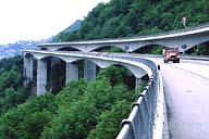
Image-GoddenA56 Chillon Viaduct, above Chillon Castle. The two parallel highways over 1 mile in length on the mountain above the castle, built in extremely difficult terrain. Construction procedure used was variable depth box girder made from precast concrete units weighing 45-80 tons each. (Lake Geneva, Switzerland) | |
|
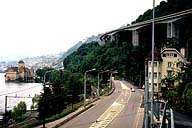
Image-GoddenA56.1 Chillon Viaduct, Lake Geneva, Switzerland. View taken at road level. (Lake Geneva, Switzerland) | |
|
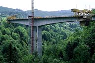
Image-GoddenA57 Elevated highway on high concrete piers near Zug, Switzerland. The girder consists of continuous variable-depth concrete box sections. View showing the construction of the girder using the balanced cantilever method, and at the stage where one pair of cantilevers is being connected to the adjacent cantilevers. (Zug, Switzerland) | |
|
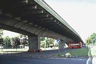
Image-GoddenA58 Hammersmith Flyover. This elevated highway is designed as a variable depth continuous concrete box girder. It is constructed from precast box and transverse cantilever section post-tensioned in situ. (London, England) | |
|
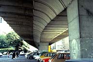
Image-GoddenA59 Hammersmith Flyover. View underneath the bridge showing the box sections that make up the main girder, and the transverse cantilevers that support the outside traffic lanes. (London, England) | |
|
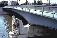
Image-GoddenA60 Pont de l'Alma over the River Seine. This unusual bridge is an extremely asymmetrical 2-span continuous beam with one very short span (near camera) and one long span to provide maximum unobstructed waterway. The beam is a variable depth welded steel box girder. (Paris, France) | |
|
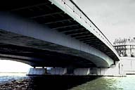
Image-GoddenA61 Pont de l'Alma over the River Seine. View underneath the bridge. Note that the bridge consists of four hollow box sections with transverse steel beams that make them act integrally and also provide a cantilevered overhang. (Paris, France) | |
|
Image-GoddenA62 Pont de l'Alma over the River Seine. Detail of internal support. This is a pinned support permitting rotation but no axial movement in the girder. Expansion bearings are fitted at both river bank supports. (Paris, France) |
 Set A: Beam Structures
