
Structural Engineering Slide Library
Box girders: constant depth
|
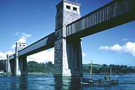
Image-GoddenA40 Britannia Bridge, Menai Straits. First railway bridge designed as deep box girder. The designer (Stephenson, 1803-59) used model experiments, ship construction practice, and included towers for adding suspension chains if necessary. Main spans 460 ft. wrought iron, total span 1511 ft. consisting of two continuous wrought iron tubes side-by-side. (North Wales) | |
|
Image-GoddenA41 Conway bridges. Tubular bridge to right is 412 ft. single span version of bridge in GoddenA40, and also by Stephenson. Theory of box girders at the time was controversial. Towers were again included for suspension chains if necessary. (North Wales) | |
|
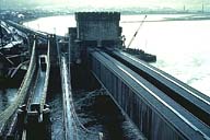
Image-GoddenA42 Approach spans, new Forth Road Bridge. Modern tubular girders. Note men on girder at far support for scale. During this construction stage a hinge was left over near support. Sections lifted by crane and welded to free end. See also construction slides in Godden Set G. (Scotland) | |
|
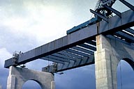
Image-GoddenA43 Composite section 3-span continuous curved highway bridge. Section consists of steel box (placed by incremental launching) and concrete roadway cast later and acting as the top flange of the section. (Flamatt, Switzerland) | |
|
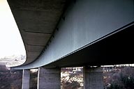
Image-GoddenA44 Composite section 3-span continuous curved highway bridge. Detail of bridge showing underside, double box construction, horizontal curvature, and intermediate supports. The two bridges are quite independent. (See GoddenA43) (Flamatt, Switzerland.) | |
|
Image-GoddenA45 Elevated highway. Taken during construction. Designed as concrete box girders, these bridges were cast in place and post-tensioned. (Vienna, Austria) | |
|
Image-GoddenA46 Kocher Valley Viaduct. Prestressed concrete box girder section used in a long multi-span incrementally launched bridge. This bridge is featured in the 'Construction' section, Godden Set G. (Neuenstadt, Germany) | |
|
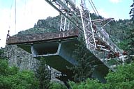
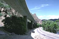
Image-GoddenA46.1 Bridge on Interstate 70. One of the 39 bridges in the 12.5-mile project under construction. The cantilever construction used a 350 ft. overhead erection gantry to lift successive precast box sections into position. Note the shear keys in the sloping webs, and the ducts for post-tensioning cables. (Glenwood Canyon, Colorado) | |
|
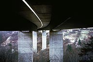
Image-GoddenA46.2 View underneath bridge on Interstate 70 (Godden46.1), showing the precast box girder and single column construction. The entire 12.5 mile project took 12 years to construct and was awarded the ASCE 1993 Outstanding Civil Engineering Achievement Award. (Glenwood Canyon, Colorado) | |
|
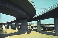
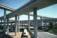
Image-GoddenA47 Highway interchange structure. Spans are all multi-cell reinforced concrete box girders. Being stiff in torsion, these sections can be supported on a single line of columns, as well as on double columns or bents. (Oakland, California) | |
|
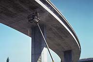
Image-GoddenA48 Expansion joint in highway interchange structure. Similar joints caused failure of curved interchange structures in San Fernando earthquake, 1971. Shows cutting square access holes in underside of box section for retrofitting joint with axial cables to prevent such failure. (Oakland, California) | |
|
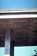
Image-GoddenA49 Close-up of expansion joint in freeway structure, showing access holes cut for retrofitting axial cables across the joint. (See GoddenA48) (Oakland, California) | |
|
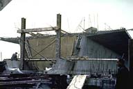
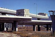
Image-GoddenA50 Unfinished highway interchange structure, near the airport. In the absence of the continuing spans, loading is left on the free cantilevered ends to limit positive moments between supports. (Near San Francisco International Airport) |
 Set A: Beam Structures
