
Structural Engineering Slide Library
Building trusses: Bracing for horizontal shear
|
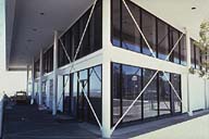
Image-GoddenD50 Single-story building. In a strongly seismic area, buildings have to resist horizontal inertial forces caused by the horizontal components of earthquake ground motions. This building has simple X-bracing in both directions. (Larkspur, California) | |
|
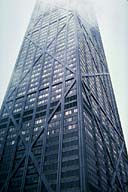
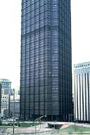
Image-GoddenD51 The John Hancock Building. This 100-story building is one of a new generation of high-rise structures where the structural system is a major consideration in the design, and where large unobstructed spaces are required inside. The main building is 1127 ft. high and consists of a tapered tube with continuous X-bracing on all four sides. In this view, the top is in cloud. (Chicago, Illinois) | |
|
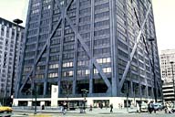
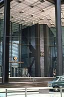
Image-GoddenD52 The John Hancock Building. Unavoidable in this solution is the appearance of the heavy X-bracing crossing window areas. Particularly at the ground level this can cause architectural problems. In this design the structural and architectural requirements were closely integrated. (Chicago, Illinois) | |
|
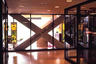
Image-GoddenD53 Close-up of the lower corner of the John Hancock Building. Note the continuity of shear bracing into the lower floor of the building. The lower shear brace in this slide continues in a below-ground shopping area shown in GoddenD54. (Chicago, Illinois) | |
|
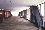
Image-GoddenD54 Continuation of the shear bracing in the basement shopping area in the John Hancock Building. The shear bracing has to be continuous from the point of origin of horizontal loading to the foundation. (Chicago, Illinois) | |
|
Image-GoddenD55 Observation deck near the top of the John Hancock Building showing the appearance created by the heavy X-bracing intersecting the window areas. Note the scale from the figure at the far end. (Chicago, Illinois) | |
|
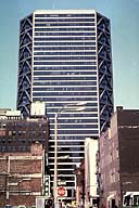
Image-GoddenD56 United States Steel headquarters building. The design differs from that of the John Hancock Bldg. in that the shear resistance of this building is taken by a large central core within the building. This 64-story structure is 841 ft. high, made of Cor-Ten steel, and triangular in plan. (Pittsburgh, Pennsylvania) | |
|
Image-GoddenD57 United States Steel Headquarters building. From the outside at ground level. The core of the building consists of a heavy vertical steel truss in a multiple panel Warren configuration. The 18 exterior columns, which provide the overall bending stiffness, are box sections filled with fluid for fireproofing. (Pittsburgh, Pennsylvania) | |
|
Image-GoddenD58 United States Steel Headquarters building. Inside the structure, showing the form of the shear bracing in the central core of the building. (Pittsburgh, Pennsylvania) | |
|
Image-GoddenD59 United States Steel Headquarters building, detail. In this design, as in the John Hancock Building, it is unavoidable that the diagonal members intersect some of the open spaces. Here one is shown cutting across a corridor opening. (Pittsburgh, Pennsylvania) | |
|
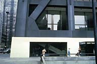
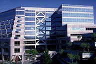
Image-GoddenD60 Alcoa Building. In this design the shear bracing is on the outside frame of the building and continues down to the first floor level. Below this the horizontal shear is transferred to a central core. The building has 26 stories and is 200 ft. x 100 ft. in plan. The columns are 50 ft. centers. (San Francisco, California) | |
|
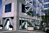
Image-GoddenD61 Detail of the Alcoa building. At this lower level the base shear is taken by the two square internal cores, and the moment resistance on the outer columns which are continuous over the height of the building. The conflicting structural (maximum shear force) and architectural (maximum open space) requirements at the base of a building result in many design solutions. (San Francisco, California) | |
|
Image-GoddenD61.1 Modern office building, Walnut Creek, California. This steel frame building in a strong seismic area uses X-bracing in upper stories to resist horizontal shear. First story shear bracing is not so visible, though one panel can be seen at the left behind the red sculpture. (Walnut Creek, California) | |
|
Image-GoddenD61.2 Close-up of part of the first story shear bracing in the structure of GoddenD61.1. The X-bracing in this slide is a window reflection of the bracing in GoddenD61.1. (Walnut Creek, California) | |
|
Image-GoddenD61.3 The British Columbia building for Expo 86. The diagonal bracing of the outer walls shows on the near section of the building. The bracing is more concealed in the larger section behind, but in places can be seen through the glass. Vancouver is in a seismic area. (Vancouver, British Columbia) | |
|
Image-GoddenD62 Medium height building. In this steel frame building the shear resistance is provided by K-bracing on the 45 degree corners. (St. Louis, Missouri) | |
|
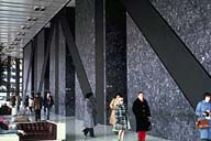
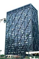
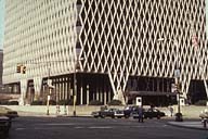
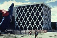
Image-GoddenD63 IBM Office Building. The outside walls of this building, which act as a tube, consist of closely spaced diagonal steel members which transmit both the horizontal and vertical loads to the base of the walls, and then to the eight support points. The steel trusses are covered wth stainless steel sheathing. (Pittsburgh, Pennsylvania) | |
|
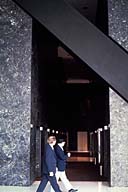
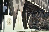
Image-GoddenD64 Detail of the IBM Office Building. Showing the near support point. The building uses steels of varying strengths, with maximum strength at the supports and reducing with increasing elevation above the supports. (Pittsburgh, Pennsylvania) | |
|
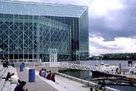
Image-GoddenD65 Exhibition Building, La Defense. The essential structure in this building in resisting both vertical loads and horizontal shear consists of diagonal members on the four outside walls and is similar to that used in the building of slide GoddenD63. (Paris, France) | |
|
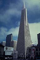
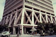
Image-GoddenD66 Transamerica Building. Height from apex to ground is 845 ft. and the base width is 175 ft. The interesting structural feature of this tapered building is the truss system above the first floor. For detail, see GoddenD67-D69. (San Francisco, California) | |
|
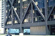
Image-GoddenD67 Base of the Transamerica Building. The truss system shown in this diagonal view supports both vertical and horizontal loading. As the building is near the San Andreas Fault, a source of major earthquakes, it is carefully engineered to take large horizontal base shear forces. (San Francisco, California) | |
|
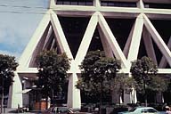
Image-GoddenD68 Transamerica Building. View of the truss system taken in a direction normal to one side. This shows the action of the truss in resisting a horizontal shear force parallel to one side. (San Francisco, California) | |
|
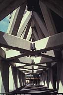
Image-GoddenD69 Transamerica Building. View at ground level, under the truss system. The overhead X-bracing resists torsional movement of the building about its vertical axis. (San Francisco, California) |
 Set D: Truss Structures
