
Structural Engineering Slide Library
Continuous beams: variable depth I-beams
|
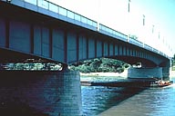
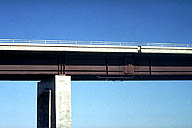
Image-GoddenA35 Plate girder bridge. This 3-span bridge is designed as a variable depth steel girder. See GoddenA36 for end support detail. (Basel, Switzerland) | |
|
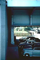
Image-GoddenA36 End support of plate girder bridge (GoddenA35) The long expansion linkage, pinned to the girder at the top and to the abutment at the bottom, permits longitudinal movement of the bridge due to thermal expansion. The direction of the end reaction is essentially vertical, being in line with the two pins. (Basel, Switzerland) | |
|
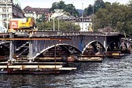
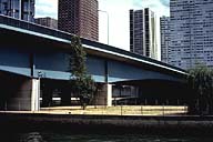
Image-GoddenA36.1 Quai Bridge. Variable depth continuous riveted steel I-beam highway bridge under construction. In addition to the vertical web reinforcement on the outside girder, note the compression web reinforcement on the inside of the left girder. (Zurich, Switzerland) | |
|
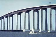
Image-GoddenA37 New Antioch Bridge. This high-level bridge completed in 1979 replaced an older truss-type lift bridge crossing the main shipping channel. The bridge consists of continuous spans of variable depth in Cor-Ten steel. Maximum span is 460 ft, and maximum height of roadway above water level is 135 ft. (California) | |
|
Image-GoddenA38 New Antioch Bridge. Detail of linkage expansion joint. This is in one of the shorter constant depth spans seen at the near end of the bridge. (See GoddenA37) (California) | |
|
Image-GoddenA39 Pont de Grenelle over the River Seine, Paris. This bridge is symmetrical and the two center supports (shown) are close together on an island in the river. The resulting short center span produces large negative bending moments in this span, and results in the maximum girder depth being in the center span. (Paris, France) |
 Set A: Beam Structures
