
Structural Engineering Slide Library
Continuous beams: constant depth I-beams
|
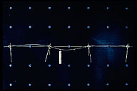
Image-GoddenA24 Simple model of a 3-span continuous beam loaded by a point load in the center span. Deflection of beam and rotation of supports (shown by pointers) illustrates location of inflexion points and the need for allowing the beam to rotate at its supports. | |
|
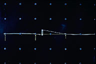
Image-GoddenA25 Flexible steel spline model used to construct an influence line for shear in the 3-span continuous beam of slide GoddenA24. The beam is cut at the point of interest and the two cut ends separated vertically by a unit distance using a deformer that holds the two cut ends parallel. | |
|
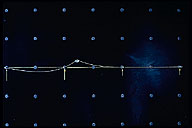
Image-GoddenA26 Spline model used to construct the influence line for moment at the same point of interest as that in slide GoddenA25. The two cut ends are given a relative rotation of one unit (radians) by the deformer. Influence lines visualized in this way are useful for determining where structures are loaded for maximum internal forces. | |
|
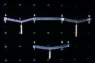
Image-GoddenA27 Two beam structures showing formation of moment hinges at collapse. Lower beam is fixed at A and simply supported at B, and develops hinges at both A and under the load. Upper beam is 3-span continuous beam and develops hinges under loads and at B and C. Both beams are statically determinate at collapse. Basis of ultimate load design of steel beams. | |
|
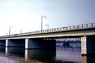
Image-GoddenA28 14th Street Bridge over the Potomac River. Continuous riveted steel girders. Note the absence of internal hinges and the resulting internal self-straining forces in the girders if one of the supports should settle. (Washington, D.C.) | |
|
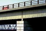
Image-GoddenA29 14th Street Bridge over the Potomac River. Detail of roller expansion bearing. Roller consists of steel roller trapped top and bottom. Note increased flange thickness at support to accommodate local high value of negative bending moment, also rivet lines of internal web stiffeners. (Washington, D.C.) | |
|
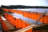
Image-GoddenA30 Continuous I-section plate girder bridge. Example of modern steel construction (1955). 3-span continuous bridge when finished, but cantilever and suspended span during construction. At this stage, the suspended spans are not yet in position in the inside girders. All welded construction. (Decatur, Illinois) | |
|
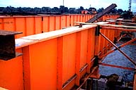
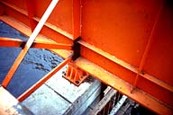
Image-GoddenA31 Continuous I-section plate girder bridge. Close-up of girder showing increased flange thickness over support for negative bending. Note the vertical web stiffener and horizontal web stiffener near lower flange over support. Note also X-bracing for transverse stability. (Decatur, Illinois) | |
|
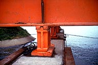
Image-GoddenA32 Continuous I-section plate girder bridge. Detail of bridge showing hinged bearing on intermediate pier. This is the fixed point of the bridge for longitudinal temperature expansion. (Decatur, Illinois) | |
|
Image-GoddenA33 Continuous I-section plate girder bridge. Detail of bridge showing rocker expansion bearing at the other intermediate pier. The convex surfaces of the rocker are visible both top and bottom. (Decatur, Illinois) | |
|
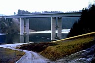
Image-GoddenA34 Continuous steel plate girder bridge. This 3-span bridge has a composite section consisting of the steel girder and the concrete roadway on top. The I-beams were fitted with shear keys as in the structure of GoddenA63. (Near Lausanne, Switzerland) |
 Set A: Beam Structures
