
Structural Engineering Slide Library
Cantilever beams and cantilever construction
|
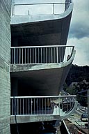
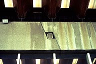
Image-GoddenA9 U.C. parking structure 'A'. The variable depth cantilever slab supports its own weight, automobile loading, and also any impact due to an automobile hitting the timber wall guard. (University of California, Berkeley) | |
|
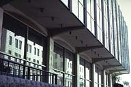
Image-GoddenA10 Building in downtown area Cincinnati. Overhang in building is supported on variable depth cantilevers. Loading on the cantilevers primarily tip loading due to outside columns. (Cincinnati, Ohio) | |

|
Image-GoddenA11 World Trade Center. Further example of building overhang supported on variable depth cantilevers. Note that adjacent cantilevers have common tip displacement. (New York City) | |
|
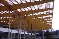
Image-GoddenA12 Entrance to stadium taken during construction. Roofing supported on variable depth glue-laminated cantilevers. Loading due to roof weight, wind, and snow. (Berne, Switzerland) | |
|
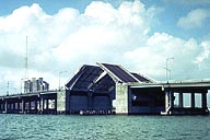
Image-GoddenA13 Bascule bridge over shipping channel. The cantilevers, shown partially raised, are designed as variable depth steel plate girders. (Miami, Florida) | |
|
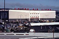
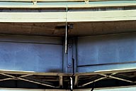
Image-GoddenA14 United Airlines Hangar. The problem of designing a long door opening without columns is common to all hangar design. Here it is accomplished using 142 ft. long variable depth symmetrical steel cantilevers. For design using trusses, see Godden Set D, and using hypar shells see Godden Set E. (San Francisco International Airport) | |

|
Image-GoddenA15 Medway Bridge during construction. The spans are cast in situ in symmetrical concrete segments about the piers, then post-tensioned. At the stage shown they act as balanced variable depth cantilevers supporting primarily their own weight. The main span consists of the two 200-ft. cantilevers shown, plus a suspended span of 100 ft. The completed anchor spans will be 312 ft. (Rochester, England) | |
|
Image-GoddenA16 Welded steel bridges. Designed as long cantilevers with short side spans and short suspended spans at mid-span. Careful inspection of image will show location of the two internal hinges in each span. Headroom calls for minimum depth beams at mid-span, dictating the location of internal hinges. (Rouen, France) | |
|
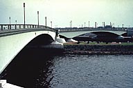
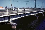
Image-GoddenA17 Elevated roadway. In this cantilever and suspended design the internal hinges are located to minimize absolute span bending moments. Locating the hinges at 0.21L from the supports produces moments of wL2/16 at supports and midspan, due to a UD loading of w/ft. (Oakland, California) | |
|
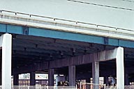
Image-GoddenA18 Close-up of hinge in elevated highway structure. [Detail of Godden A17] (Oakland, California) | |
|
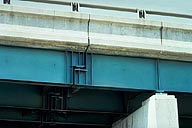
Image-GoddenA19 Approach spans, Carquinez Bridge. Detail of linkage expansion joint in a steel plate girder. Bridge is curved in plan. Note longitudinal stiffeners on the compression side of each girder. Linkage is in tension. This joint transmits shear but ensures zero moment and zero axial force at the joint in both girders. (San Francisco Bay Area) | |
|
Image-GoddenA20 Early variable depth steel girder bridge. Interestingly, the locations of the internal expansion linkages (see left of near support) were not selected to minimize the positive moments at midspan where the girder depth is minimum. (Boston, Massachusetts) | |
|
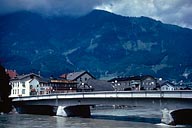
Image-GoddenA21 Concrete highway bridge, Austria. Note the symmetrically placed hinges in the main span that make this bridge statically determinate. (Austria) | |
|
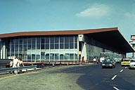
Image-GoddenA22 Terminal Building. The trapezoidal section concrete beams supporting the roof are constructed on the cantilever and suspended span method to minimize the internal bending moments. (Rome International Airport) | |
|
Image-GoddenA23 Terminal building. Detail of internal hinge in concrete beam [Detail of GoddenA22] (Rome International Airport) |
 Set A: Beam Structures
