
Structural Engineering Slide Library
Neckar Valley Viaduct, Weitingen , Germany (1978)
|
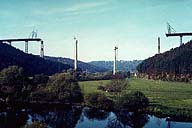
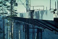
Image-GoddenG43 Neckar Valley Viaduct. View of the unfinished bridge, taken from the valley floor. The 233.8 m and 263.2 m spans are being cantilevered and supported on steel false-work bents. At this stage they have almost reached the permanent double-shafted piers. The two single-shafted intermediate piers will support the three shorter 134.3 m spans. GoddenG44-G50 were taken of, or from, the right hand span. (Weitingen, Germany) | |
|
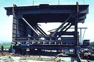
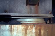
Image-GoddenG44 Neckar Valley Viaduct. 72-ft length of the steel box girder section. Note the orthotropic construction and the scale of the section from the figure at the left. This length of girder is ready to be moved by rail to the cantilevered end, lowered into position by the construction crane, and connected. (Weitingen, Germany) | |
|
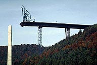
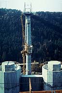
Image-GoddenG45 Neckar Valley Viaduct. Close-up of the right hand span of slide GoddenG43, showing the two temporary steel towers and the cantilevered end. The king post for the inverted cables can be seen at the right hand temporary support. The tower on the left is the double-shafted tower that provides torsional restraint to the girder as well as vertical support. (Weitengen, Germany) | |
|
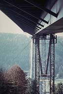
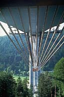
Image-GoddenG46 Neckar Valley Viaduct. View from the end abutment showing the underside of the box girder, the angled struts supporting the cantilevered section of the deck, the falsework bents that support the end span during construction, and the two inclined struts of the king post connected to the underside of the girder at midspan. (Weitingen, Germany) | |
|
Image-GoddenG47 Neckar Valley Viaduct. Side view of the end span taken from near the abutment. A careful study of this slide shows the negative curvature of the girder at this cantilever phase. (Weitingen, Germany) | |
|
Image-GoddenG48 Neckar Valley Viaduct. Taken from the cantilevered end of the end span, looking down into the valley floor towards the far abutment. The nearest support is the two-shafted pier that will support the end span. Next are the two single-shafted hexagonal piers that will support the three center spans. The far-side end span and its two-shafted pier can be seen in the distance. (Weitingen, Germany) | |
|
Image-GoddenG48.1 Neckar Valley Viaduct. View under the girder from one abutment showing the cables passing from the girder anchorage at the abutment, under the mid-span king post shown in GoddenG46, and then to the girder anchorage at the next column support. (Weitingen, Germany) | |
|
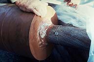
Image-GoddenG49 Neckar Valley Viaduct. Close-up of the cable with its integral end block that will provide the anchorage. (Weitingen, Germany) | |
|
Image-GoddenG50 Neckar Valley Viaduct. Close-up of the end span abutment support. One end of the bridge is fixed in position, and the other end (shown) is a sliding bearing with a maximum travel of 5.0 in. (Weitingen, Germany) | |
|
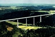
Image-GoddenH11 Neckar Valley Viaduct, overview. (Weitingen, Germany) |
 Set G: Structures Under Construction
