
Structural Engineering Slide Library
Kocher Valley Viaduct, Neuenstadt, Germany (1972)
|
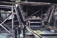
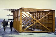
Image-GoddenG34 Kocher Valley Viaduct. Section of the bridge consists of a deep concrete box girder. Unit lengths of the girder were cast under carefully controlled conditions in a temporary building at one end of the bridge.This slide shows the formwork inside the building, and the rails via which the completed section will be moved to the end of the bridge. (Neuenstadt, Germany) | |
|
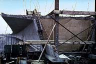
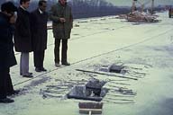
Image-GoddenG35 Kocher Valley Viaduct. This slide shows the end of the launched bridge to which the next section will be connected. A careful study of this slide will show the long curved length of the bridge that has already been launched section by section. (Neuenstadt, Germany) | |
|
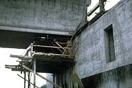
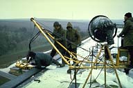
Image-GoddenG36 Kocher Valley Viaduct. Close-up of the end of the girder in GoddenG35 taken from beneath. The launching process consists of pushing the entire girder out from the construction end using hydraulic jacks. This slide shows the jack in a horizontal position supported by the yellow frame. The launching force is reacted against the abutment. (Neuenstadt, Germany) | |
|
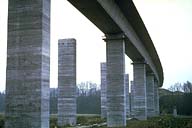
Image-GoddenG37 Kocher Valley Viaduct. Taken from the valley floor, this slide shows the launched right hand bridge, and the free-standing piers of the left bridge. The girder, during launching, slides on pads at the pier tops, and at the time this picture was taken the right bridge had been launched over 7 of the 9 spans. (Neuenstadt, Germany) | |
|
Image-GoddenG38 Kocher Valley Viaduct. To reduce the weight of the cantilevered end in such a launching procedure, a light-weight launching nose is used at the free end. In this case it is a light plate girder construction (yellow) shown resting on the deck of the box girder section. (Neuenstadt, Germany) | |
|
Image-GoddenG39 Kocher Valley Viaduct. Post-tensioning operations include overall span post-tensioning. This slide shows the anchorage points for two longitudinal tendons, recessed in the top flange, and in line with the inside face of the sloping web of the box section. (Neuenstadt, Germany) | |
|
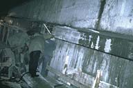
Image-GoddenG40 Kocher Valley Viaduct. View inside the concrete box girder showing the profile of the outstanding duct for the post-tensioning tendons. The 'wall' in this slide is the inside surface of the box girder web. The junction between the web and the deck slab can be seen at the top left and indicates that the cables will break the top surface of the deck just off the slide to the left. (Neuenstadt, Germany) | |
|
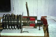
Image-GoddenG41 Kocher Valley Viaduct. Demonstration specimen showing a typical prestressing tendon anchorage that is cast in concrete as seen in GoddenG39. (Neuenstadt, Germany) | |
|
Image-GoddenG42 Kocher Valley Viaduct. Transverse post-tensioning is also applied across the deck. This slide shows the tensioning jack suspended in a horizontal position outside the edge of the deck by a small tubular crane (both yellow). (Neuenstadt, Germany) |
 Set G: Structures Under Construction
