
Structural Engineering Slide Library
Fabricating prestressed concrete beams
|
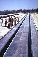
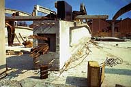
Image-GoddenA74 Long-line steel formwork used for end-to-end fabrication of the beams of GoddenA75. A single pretensioning is used for the entire length, and is subsequently cut at the junction between the beams. | |
|
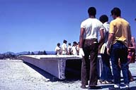
Image-GoddenA75 Prestressed beams constructed in the formwork shown in GoddenA74. Here beams are supported on blocks at each end, and in spite of dead load, have a residual upward curvature seen by looking along top flange. Curvature due to transfer of pretensioning force to beam in the form of prestress. | |
|
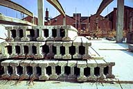
Image-GoddenA76 Prestressed I-section purlins made on the same pretensioning principle as the beams of GoddenA75. Again upward curvature can be seen. | |
|
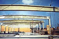
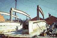
Image-GoddenA77 Post-tensioned concrete roof beams. In this design the cable duct is straight and the beam has an upward curvature providing the required variation in cable eccentricity relative to the section center of gravity. Beams are simply supported at both ends on columns. (Belfast, Northern Ireland) | |
|
Image-GoddenA78 Post-tensioned concrete roof beams. Beam is first cast in formwork on the ground, formwork is removed, and prestressing rods inserted. Note upward curvature of beam axis. (Belfast, Northern Ireland.) | |
|
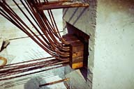
Image-GoddenA79 Post-tensioned concrete roof beams. Rods are anchored at one end of beam and tensioned at the other by hydraulic jack, then anchoring wedges are driven home (Magnel system). (Belfast, Northern Ireland) | |
|
Image-GoddenA80 Beam is now carrying its full prestressing force. Note in comparison with GoddenA78 that the beam has now deflected upward at the center (seen by the black separation line between beam and ground), the upward deflection being caused by the prestressing force. (Belfast, Northern Ireland) |
 Set A: Beam Structures