
Structural Engineering Slide Library
Oakland Coliseum Arena (1966)
|
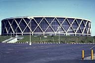
Image-GoddenG18 Oakland Coliseum Arena. Outside view of the completed arena. Oakland is in a highly seismic zone, and the continuous X-columns that support the ring beam also resist the inertia forces caused by the entire roof mass being accelerated by any direction of ground motion. (Oakland, California) | |
|
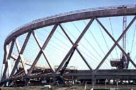
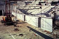
Image-GoddenG19 Oakland Coliseum Arena. View outside the arena. The X-columns, concrete ring beam, cables, and central tension ring have been constructed, and the work is starting on lifting the concrete ribs that rest on the cable. (Oakland, California) | |
|
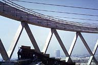
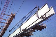
Image-GoddenG20 Oakland Coliseum Arena. Inside the arena, showing the connection between the steel cables and the ring beam. The scale can be seen from the figures on the arena seating in the foreground. (Oakland, California) | |
|
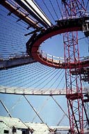
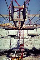
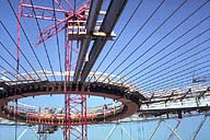
Image-GoddenG21 Oakland Coliseum Arena. Inside the arena showing the central steel tension ring (red) and the cable anchorage on the inner face of the ring. Note the crane used for lifting the concrete ribs passing through the center of the ring. (Oakland, California) | |
|
Image-GoddenG22 Oakland Coliseum Arena. Lifting the 90-ft long precast concrete ribs from the floor of the arena through a gap on the radial cables made by omitting one cable. Note the scale of the rib from the figure directly beneath. The web thickness of the rib is a mere 2.0 in. The near end of the beam will be connected to a similar beam to form a full 180-ft rib. (Oakland, California) | |
|
Image-GoddenG23 Oakland Coliseum Arena. The concrete rib of slide GoddenG22 has now been lifted through the cables and is being lowered onto one of the cables (it is the right of the two beams shown). The rib has a groove in the lower flange to receive the cable. The left beam is already in position. (Oakland, California) | |
|
Image-GoddenG24 Oakland Coliseum Arena. The ribs were erected in pairs and braced together for lateral stability during the construction phase. Final stability is achieved by the transverse diaphragms shown unconnected in this view. (Oakland, California) | |
|
Image-GoddenG25 Oakland Coliseum Arena. To maintain a symmetrical loading pattern during construction, and a relatively uniform tension on the ring beam, the ribs were erected in a uniform pattern. At this stage there are single rib-pairs north, south, east, and west. (Oakland, California) | |
|
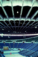
Image-GoddenG26 Oakland Coliseum Arena. Inside view of the completed arena taken in daylight. Note the form of the completed roof with the radial ribs and circumferential diaphragms. (Oakland, California) | |
|
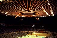
Image-GoddenG27 Oakland Coliseum Arena. Inside view of the completed arena taken after dark in artificial lighting. The form of the roof is particularly striking in this light. This view shows the arena being used for basketball. (Oakland, California) |
 Set G: Structures Under Construction
