
Structural Engineering Slide Library
Cable-roof structures
|
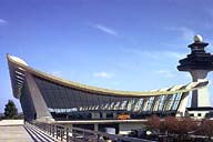
Image-GoddenC66 Airport Terminal Building, Dulles International Airport. This cable roof structure with a span of 141 ft. was designed by Eero Saarinen. It is constructed on a modular plan. (Washington, D.C.) | |
|
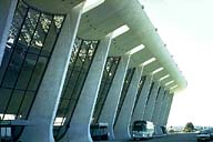
Image-GoddenC67 Detail of pier supports in Dulles Airport Terminal building. Point of connection of roof cable to the pier is 49.5 ft. above ground. Increasing width of pier towards the ground is due to the resultant cable force at its point of connection. Compare this with a medieval cathedral buttress that also increases in width towards its base. (Washington, D.C.) | |
|
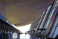
Image-GoddenC68 Interior of Dulles Airport Terminal. The tension in the roof cable is balanced by a horizontal thrust taken at the level of the floor in this slide. (Washington, D.C.) | |
|
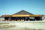
Image-GoddenC69 Small tension structure for a coffee shop. Note the cables radiating from the apex of the building to the edge beams. (Spokane, Washington) | |
|
Image-GoddenC70 Alitalia hangar. Cable-stayed roof design. (Rome International Airport) | |
|
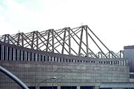
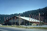
Image-GoddenC71 Cable-stayed roof. Built for the Winter Olympic Games, this building encloses the ice-rink. The roof span is 300 ft. and the apex height is 85 ft. 4 in. above floor level. Maximum snow load of 100 psf is reduced to 50 psf by pumping warm air through the cells of the roof deck. (Squaw Valley, California) | |
|
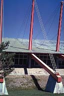
Image-GoddenC72 Detail of anchorage, cable arrangement, and steel posts for ice-rink roof. The cables are three 2.25 in. diameter bridge strands: two go to the farthest anchor point on the roof, and one to the nearest. Steel posts are tapered section consisting of four-flanged cross-shaped sections. Under dead load they were prestressed backwards so as to be straight under maximum live load. (Squaw Valley, California) | |
|
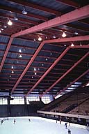
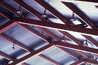
Image-GoddenC73 Inside of the ice-rink arena structure. The roof is supported on cable-stayed steel box girders which are connected together at mid-span only by a horizontal sliding joint. The box girders are 2 ft. wide and taper in depth from 2 ft. at the apex to 3 ft. 6 in. at the base of the steel posts. (Squaw Valley) | |
|
Image-GoddenC74 Close-up of the mid-span joint in the ice-rink's roof structure. The joint between the beams at the apex of the roof allows relative horizontal movement but no relative vertical movement between the ends of the beams. Note also the cable anchorage towards the right in the near beam. At maximum live load, vertical deflection of apex is 22 in. (Squaw Valley) |
 Set C: Cable and Suspension Structures
