
Structural Engineering Slide Library
Cable-stayed bridges
|
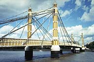
Image-GoddenC54 Albert Bridge across the River Thames. One of the earliest cable-stayed bridges, it opened in 1873. The spans are 147 ft, 384 ft, and 147 ft. Width of the bridge is a little over 41 ft. (London, England) | |
|
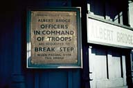
Image-GoddenC55 A notice at the end of the Albert Bridge requests that soldiers 'break step' when crossing, indicating that the possibility of a resonant effect was recognized. Dynamic effects can be important in cable structures on account of their potential flexibility and consequent low natural frequencies. (London, England) | |
|
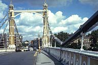
Image-GoddenC56 The Albert Bridge was strengthened in 1884 by replacing the wire ropes with the steel link chains of the present bridge. The structure used both curved and straight chains. The bridge now has a mid-span support in the river enabling it to take modern traffic loading. (London, England) | |
|
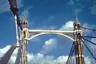
Image-GoddenC57 Albert Bridge. Detail of the tower top and cables. The straight cables are kept straight by being supported on the curved cables above. The bridge has been preserved for historic and aesthetic reasons only. (London, England) | |
|
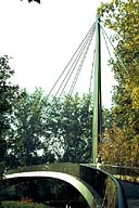
Image-GoddenC58 Small cable-stayed footbridge. This is an early example of the cable-stayed bridge construction that became prominent particularly in German design practice since World War II. This simple bridge has 'fan' cable configuration. The girder is a Y in plan: the main span across the roadway being the stem of the Y, and this divides into two curved arms of the Y at the near end. (Stuttgart, Germany) | |
|
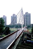
Image-GoddenC58.1 Pedestrian bridge over the River Neckar in Mannheim (1975). Double line of inclined cables are suspended from the top of the two steel towers on the bridge axis. Main span (see GoddenC58.2) is 140 m; side spans are 57 m. The deck is a concrete slab. (Mannheim, Germany) | |
|
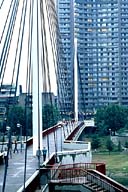
Image-GoddenC58.2 Close-up of main span and cable system in GoddenC58.1. The pedestrians give a sense of scale. (Mannheim, Germany) | |
|
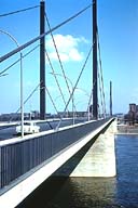
Image-GoddenC59 Cable-stayed highway bridge. Completed in 1958, this bridge used the 'harp' cable arrangement. Spans are 108 m, 260 m, and 108 m. Tower height is 40 m above roadway. (Dusseldorf-North, Germany) | |
|
Image-GoddenC60 Cable-stayed highway bridge over the River Rhine. This bridge is also designed on the parallel cable 'harp' arrangement. Spans are 104 m, 255 m, and 104 m. Tower height is 43 m above roadway. (Rees, Germany) | |
|
Image-GoddenC61 Cable-stayed concrete bridge. This modern bridge which crosses the Danube Canal was made in two self-supporting halves, each balanced on one pier, and each parallel to the canal bank. The halves were then rotated on the pier and connected at midspan. The spans are 55 m, 129 m, 55m. (Near Vienna, Austria) | |
|
Image-GoddenC62 Cable-stayed concrete bridge. Detail shows the section of the girder comprised of prefabricated hollow box elements. The girder was finally post-tensioned over its entire length. (Near Vienna, Austria) | |
|
Image-GoddenC63 Cable-stayed concrete bridge. Detail shows the anchorage of the four parallel cables at the girder side-span. (Near Vienna, Austria) | |
|
Image-GoddenC64 Cable-stayed concrete bridge. Support detail at the end abutment. The shortening of the bridge on the cold day this slide was taken can be seen by the shear deformation of the laminated neoprene support block. (Near Vienna, Austria) | |
|
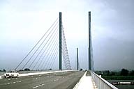
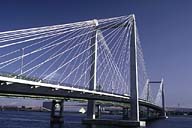
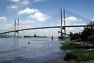
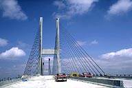
Image-GoddenC64.1 Pasco-Kennewick cable-stayed highway bridge over the Columbia River, Washington State. Completed in 1978. Spans are 124-300-124 meters. Towers are reinforced concrete, the deck is prestressed concrete. See also GoddenH60 and GoddenH61. (Kennewick, Washington) | |
|
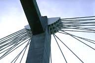
Image-GoddenC64.2 Detail of top of tower in bridge of GoddenC64.1, showing the cable connections. (Kennewick, Washington) | |
|
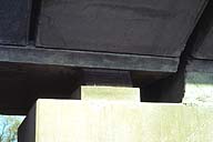
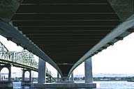
Image-GoddenC64.3 View underneath the deck system of the bridge of slide GoddenC64.1, taken from one abutment. Note that overall torsional system of the deck is not as important when two lines of cables are used. Compare this with the Rhine bridge at Flehe (GoddenC64.4 and GoddenC64.5) which uses a single line of cables. (Kennewick, Washington) | |
|
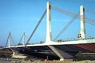
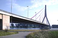
Image-GoddenC64.4 Rhine River Bridge at Flehe, near Dusseldorf, Germany. Single tower design. The single line of cables is connected to the center of the deck, and there are three traffic lanes on each side. This arrangement depends on the torsional stiffness of the deck structure for overall stability. (Dusseldorf, Germany) | |
|
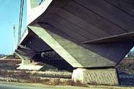
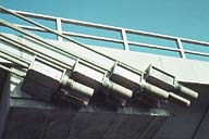
Image-GoddenC64.5 Detail of the deck structure in GoddenC64.4. Note the large continuous steel box section along the center line of the bridge, providing the required torsional stiffness. Note also that the large tensile force in the cable back-stays is taken by tension in the column supports to the deck beyond the tower. (Dusseldorf, Germany) | |
|
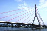
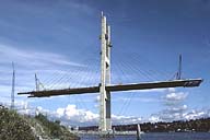
Image-GoddenC64.6 Alex Fraser Bridge over the Fraser River near Vancouver, British Columbia, designed by Buckland and Taylor. Constructed by the "balanced cantilever" method, the girder is built in sections, balanced about the towers. A partially completed section can be seen at the end of the cantilever, but the associated cables have not been connected. Note the lower cables to stabilize the tower at this stage. (Fraser River near Vancouver, B.C.) | |
|
Image-GoddenC64.7 Alex Fraser Bridge, completed in 1986. Overall dimension: spans, 182-465-183 m; height of towers, 153.8 m; height of road above water, 54.6 m. There are 192 cables in two vertical lines, arranged as a "modified fan", between the standard "fan" and "harp" layouts. (Fraser River near Vancouver, B.C.) | |
|
Image-GoddenC64.8 Main span of Alex Fraser Bridge at road level during final stages of construction, showing cable layout. Cables are connected to the ends of the transverse steel floor beams which can be seen in GoddenC64.6. (Fraser River near Vancouver, B.C.) | |
|
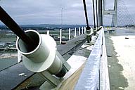
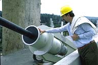
Image-GoddenC64.9 Main span of Alex Fraser Bridge at road level showing the cable anchorages. The steel tube at each anchorage will contain a visco-elastic damper to control cable vibrations. Also, the end of each cable is left visible in order to check on possible creep in the anchorage. (Fraser River near Vancouver, B.C.) | |
|
Image-GoddenC64.10 Alex Fraser Bridge. Close-up of one cable anchorage fitted with its cable damper. (Fraser River near Vancouver, B.C.) | |
|
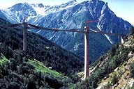
Image-GoddenC64.11 Ganter Bridge spanning an Alpine valley, near the Simplon Pass in Switzerland, and shown during construction. Designed by Christian Menn, this is an interesting example of a cable-stayed bridge, though the cables are inside a thin concrete wall. The overall layout of the bridge is S-shaped in plan, the 174 m main span is straight, but the side spans, including the back-stay cables, have 200-m radius curves. The taller pier is 150 m high. The appearance of the center span between piers is not unlike the inverse of the arch structure in GoddenB28.1 designed by Maillart. (Simplon Pass, Switzerland) | |
|
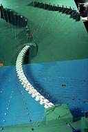
Image-GoddenC65 The 'Ruck-A-Chucky' Bridge, designed to span the middle fork of the American River by T. Y. Lin International. Girder is 1300 ft. span box girder with horizontal curvature, supported on 48 cables individually anchored to the canyon wall. Picture shows a 1/200th scale dynamic model for studying earthquake response. |
 Set C: Cable and Suspension Structures
