
Structural Engineering Slide Library
Modern bridges: flexible and stiffened
|
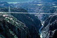
Image-GoddenC21 Royal Gorge Bridge. This bridge is included because of its flexibility that enables truss deflections to be seen (and felt) as the traffic moves across the span. It is also the highest such bridge, being 1035 ft. above water level. The north and south towers are 110 and 150 ft. high respectively, and the spans are 190-938-130 ft. The original bridge was built in 1929. It was refurbished in 1984. (Colorado) | |

|
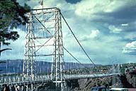
Image-GoddenC22 Royal Gorge Bridge towers. The bridge consists of light steel towers, a flexible stiffening truss, steel cables, and timber decking. The cables are attached to roller saddles at the top of the towers, thus inducing no lengthwise horizontal forces in the towers. The deck structure is suspended from the cable steel rods. (Colorado) | |
|
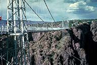
Image-GoddenC23 Royal Gorge Bridge with an automobile at the midspan. The very small depth of the stiffening truss can be seen, together with the great height of the bridge above the canyon. (Colorado) | |
|
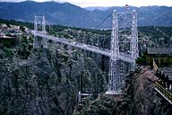
Image-GoddenC24 Royal Gorge Bridge. The deflected shape of the truss under the action of a mid-span load can be seen by observing the dark line of the lower chord of the truss. The downward deflection at mid-span, together with an associated upward deflection at the quarter-spans are typical of suspension bridge behavior. (Colorado) | |
|
Image-GoddenC24.1 The refurbished bridge includes a transverse curved wind cable system attached to the deck structure (seen to the left of the near tower base). Due to buckling and fatigue in the suspender rods, these were replaced with steel rope suspenders. (Colorado) | |
|
Image-GoddenC24.2 A new anchorage system was installed as corrosion was developing in the wires of the original anchorage. As the saddle rollers had become frozen, the towers were stabilized to take the horizontal forces transmitted by the cables at the top. (Colorado) | |
|
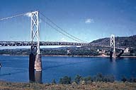
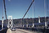
Image-GoddenC25 Maysville suspension bridge. This moderate-sized bridge over the Ohio River illustrates the component parts of a typical suspension bridge. The stiffening truss is a continuous 3-span warren through truss. The symmetrical shear bracing of the warren truss is typical as shear changes sign with loading position. (Maysville, Kentucky) | |
|
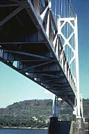
Image-GoddenC26 Maysville suspension bridge. Underside of the stiffening truss. Warren-type wind bracing between lower chords of the truss. Heavy shear bracing at the bottom of the tower transmits transverse loading due to wind or earthquake (there was a 5.1 earthquake on 7/27/80 ) from the road level to the top of the piers. (Maysville, Kentucky) | |
|
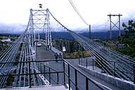
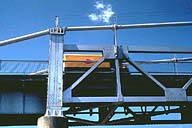
Image-GoddenC27 Maysville suspension bridge. View along roadway of the bridge showing wind bracing in the towers, single cable design, and the hanger arrangement. (Maysville,Kentucky) | |
|
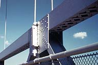
Image-GoddenC28 Maysville suspension bridge. Detail of the hanger-truss connection. Shows the riveted connection in the stiffening truss, the top chord consisting of braced double channels, and the shear bracing consisting of I-sections. (Maysville, Kentucky) | |
|
Image-GoddenC29 Maysville suspension bridge. Detail of the end post. The post is hinged at the base by a curved steel bearing pad, and is connected to the cable at the saddle on top. Heavy compression in the post is primarily due to the change in angle of the cable at the saddle. (Maysville,Kentucky) |
 Set C: Cable and Suspension Structures
